by | Jun 17, 2015 | Calibration Instruments, New Products, Our Instruments
Description MSC-1015 is a battery operated instrument that is used to electronically simulate variety of outputs from various types of sensors. MSC-1015 uses a menu-driven 4×16 character LCD display to establish appropriate settings. The key panel contains five sealed switches marked with arrows, E (Enter), Back and ON/OFF. Power is supplied from 4 AA rechargeable, internally mounted Ni-MH batteries which can be recharged with a regulated 9Vdc source. Connection to PC is established over the front mounted LEMO connector. PC mode will be automatically started after inserting proper cable into device. Output signal is user selectable from: single-ended voltage (mV), single-ended charge (pC), differential charge (pC), current-sinking IEPE (ICP®), loop powered current source (mA), tachometer (TTL), flow (TTL), OSO® (Optical Speed Output) and BOV (Bias Output Voltage). Frequency range is 1Hz to 10kHz; RMS output voltage is from 10mV to 10V or 10pC to 10.000pC. Outputs can be provided in acceleration, velocity, displacement, voltage or charge. Application note Suitable for inspecting measurement lines according to ISO 10816 standards. Device is especially designed for Condition Monitoring Systems (CMS) and/or Vibration Monitoring Systems (VMS) that are independent or connect to SCADA Systems. Features Datasheet Software User Manual Specification Simulates various sensor signals Loop powered current source output Tachometer TTL and OSO® output BOV sensor test Menu-driven operation Multi language menu Metric and imperial units PC connection Battery operated MSC-1015 DT v03 – –...

by | May 13, 2015 | Other Products, Our Instruments
TI-100 is a PC based TEDS reader/writer. It can be used to read or write TEDS information in supported vibration sensors. Software coverage two templates (0.9 and 1.0) of IEEE 1451.4 standard for smart transducers interface. It is designed to read/write TEDS information from sensors with mixed mode communication protocol in version 0.9 and 1.0. Templates supported by this software are: Template 0 for IEEE 1451.4 standard version 0.9 Template 1 for IEEE 1451.4 standard version 0.9 Template 24 for IEEE 1451.4 standard version 0.9 Template 25 for IEEE 1451.4 standard version 1.0 In both cases this is an accelerometer with IEPE supply. Device is Plug & Play and USB powered. On sensor side it has a 10-32 (microdot) connector for sensor connection. PC software is easy to use and simple with an upgrade possibility. It can also store sensor information in the file. Features Datasheet Software User Manual Specification Reading TEDS information from sensor Simple write new TEDS information All IEPE accelerometer support Supported standard version 0.9 and 1.0 PC based Easy to use software USB powered Plug & Play device TI-100 DT v04 TI-100 v1.3 – Outputs Type: USB – PC connection and power supply 10-32 (microdot) – Sensor connection Environmental characteristics Temeperature: Operating: -10°C to +65°C Storage: -18°C to +65°C Humidity: 95% R.H. maximum Physical characteristics Dimension: 51mm x 25.4mm x 12.7mm Weight: 5og typical Case: Oblikovana plasti?na kutija Connections: USB, 10-32 microdot ...
by | May 13, 2015 | Our Instruments, Test Instruments
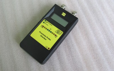
PC-100 Proximity Probe Checker is a battery operated, easy to use instrument which checks sensor GAP and then indicates it on the LED bar integrated on the front panel. There is also a LCD screen for displaying GAP voltage for better accuracy. PC-100 can also be used to simulate any current sensor with constant current output. Power is supplied by one internally mounted 9V alkaline battery. Working mode can be selected by a side switch mounted on the left side. There is also a visual identification of the selected mode placed on the front panel. The measured voltage is displayed on LCD screen and on LED diodes, which indicates the position of proximity sensor. It is especially designed for fast checking of proximity probes used in the monitoring system. It also helps the operator to set up proximity probe in optimal position and/or to get information about the probe position in front of the shaft. In CURRENT SOURCE mode, the instrument produces fixed current of 12mA. It is designed to get external 24V on this input and it generates fixed current through integrated current loop. Features Datasheet Software User Manual Specification Proximity GAP checker Current senzor simulator Easy to use LCD for reading measured voltage LED indication for sensor GAP Side switch for mode selection Empty battery detection PC-100 DT v04 – PC-100 UM v5.3 Outputs Type: Proximity sensor input Current loop output Signal generation Amplitude: 12mA, DC Current accuracy: ±0.5% Environmental characteristics Temperature: Operating: -10°C to +65°C Storage: -18°C to +65°C Humidity: 95% R.H. maximum Power Battery: 1 x 9V Alkaline 9V (6LR61) battery Autonomy: >8h, GAP TEST...
by | May 13, 2015 | Our Instruments, Sensor Simulators
MSS – 1010 is a battery operated instrument that is used to electronically simulate variety of outputs from various types of accelerometers. MSS-1010 uses a menu-driven 4×16 character LCD display to establish appropriate settings. The key panel contains five sealed switches marked with arrows, E (Enter), Back and ON/OFF. Power is supplied by 4AA internally mounted rechargeable Ni-MH batteries, which can be recharged with a regulated 9Vdc source. Connection to PC is established over the front mounted LEMO connector. PC mode will be automatically started after inserting proper cable into device. Output signal is user selectable from: single-ended napon (mV), single-ended ®charge (pC), differental charge (pC), current-sinking IEPE (ICP), tachometer (TTL), ®flow (TTL), OSO (Optical Speed Output) and BOV (Bias Output Voltage). Frequency range is 1Hz to 1kHz; output voltage RMS is from 10mV to 10V or 10pC to 10.000pC. Outputs can be provided in acceleration, velocity, displacement, voltage or charge. Application note Suitable for inspecting measurement lines according to ISO 10816 standards. Device is especially designed for Condition Monitoring Systems (CMS) and/or Vibration Monitoring Systems (VMS) that connect to SCADA Systems. Features Datasheet Software User Manual Specification Simulates accelerometer signals Tachometer TTL and OSO® output BOV sensor test Menu-driven operation Multi language menu Metric and imperial units PC connection Battery operated MSS-1010 DT v02 – MSS-1010 UM v03 Outputs Type: Single-ended voltage (mV) IEPE (ICP®) – current sinking Single-ended charge (pC) Differential charge (pC) Tachometer (TTL) Flow meter (TTL) OSO® – Optical Speed Output BOV – Bias Output Voltage Signals generator Frequency range: 1Hz – 1kHz, accuracy ±1% Amplitude: Adjustable up to 10 000mV RMS Distortion...

by | May 13, 2015 | Our Instruments, Sensor Simulators
SC-100 Sensor Checker is a battery operated, easy to use instrument for checking sensor condition by measuring bias voltage and for electronically simulating IEPE sensor output from accelerometers. Power is supplied by one internally mounted 9V alkaline battery. There is also a LED indication of low battery. Working mode can be selected by a side switch mounted on the left side. There is also a visual identification of the selected mode placed on the front panel. Depending on the bias voltage, the following predefined statuses are possible: In BOV TEST mode user can read measured bias voltage on the screen and sensor status on the LED diodes on the front panel. There are predefines sensor status which are depending from the bias voltage and they are: short circuit, sensor ok and open circuit. For short circuit, measured bias voltage is below 7V. For open circuit measured bias voltage is more than 15V. For sensor ok, measured bias voltage is between 7V and 15V. If the customer wants different voltage levels, changes are possible free of charge before shipment. In SIGNAL GENERATOR mode, the instrument produces fixed frequency sinusoidal signal to simulate accelerometers or velocity meter output. Parameters for checking (for sensor sensitivity 100mV/g) 160 Hz Units RMS PEAK mV 100 141.4 m/s² 9.81 13.87 g 1 1.41 mm/s 9.75 13.79 ips 0.38 0.54 Features Datasheet Software User Manual Specification BOV sensor test Simple IEPE sensor simulator Easy to use LCD for reading measured voltage LED indication of sensor status Side switch for mode selection Empty battery detection SC-100 DT v04 – SC-100 UM v7.2 Outputs Type: ®IEPE (ICP...